
PFAS + PFOS Scrub and Destroy by Electro-Kinetic Graphite Electrodes
All Rights Reserved, US 63/716,917
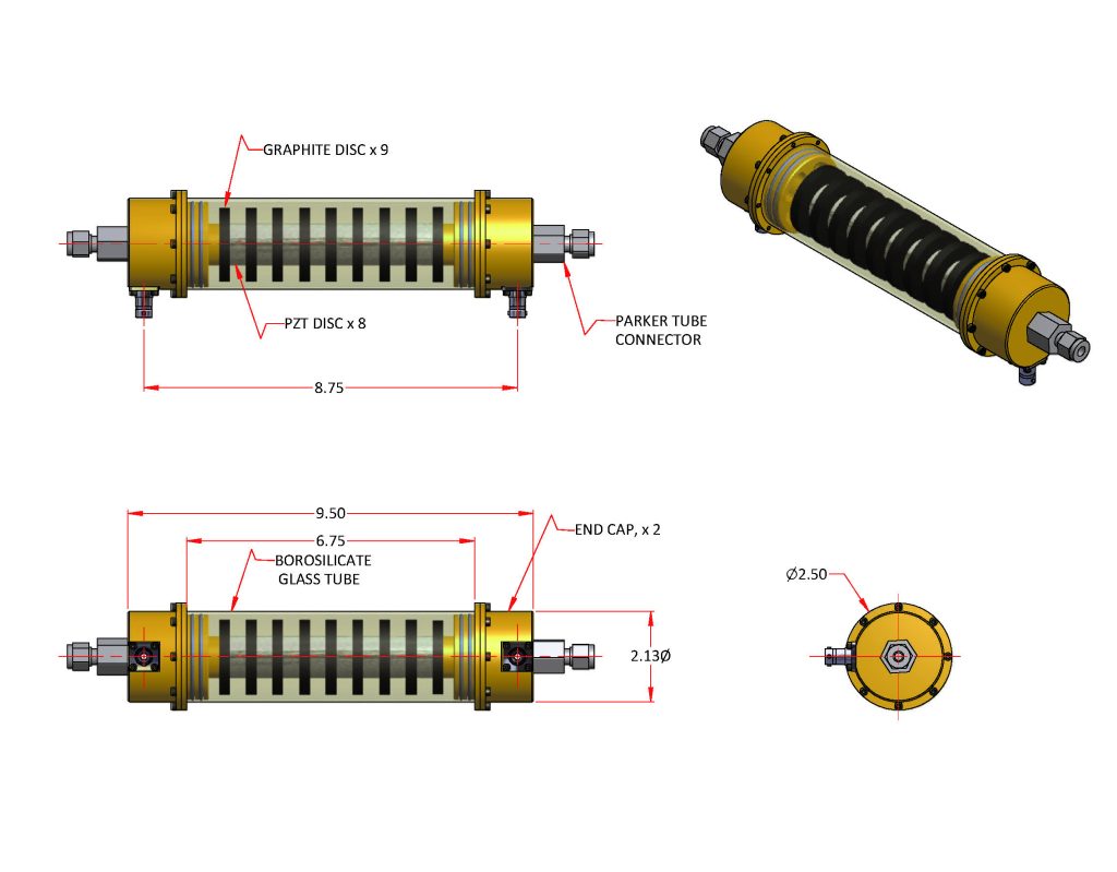
AutoDesk Inventor 3D Model
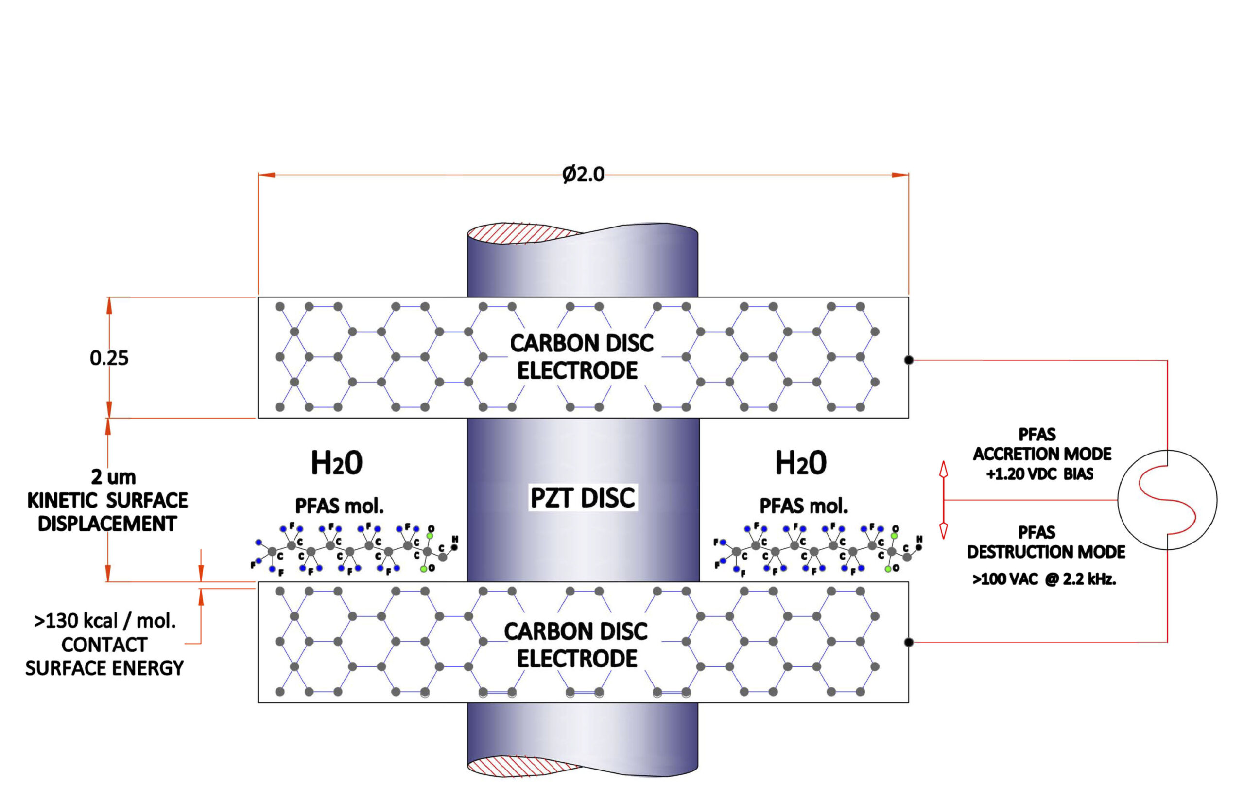
Carbon disc surfaces are charged to a static 1.20 VDC. bias while in the “Scrub” mode, then switch to “Destroy” mode after an elapsed period of time to high voltage A.C. for about two minutes.

The commercial prototype is currently under development as the phase two SDS-100 build based on our initial lab data results, then to CSA / UL pending certification at the Rexdale Ontario Canada facility.

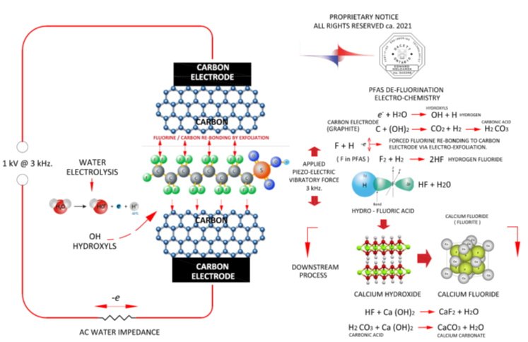
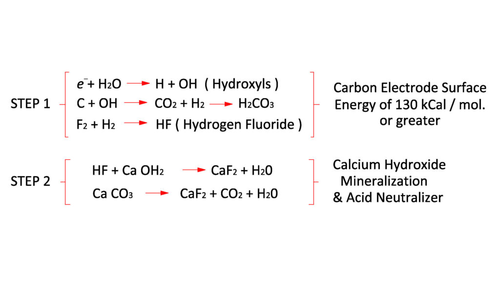
“Carbon surfaces passively scrub waterborne PFAS molecules then periodically Electro-Kinetic energy is applied to the carbon surfaces when the accumulated concentration of PFAS becomes high enough over time. Piezo Electric Transducers (PZT’s) then vibrate the graphite disc electrodes generating surface energies surpassing 130 kcal /mol, destroying PFAS particles instantly having been previously captured and accreted thereupon said carbon surfaces. Both electric charge and kinetic vibration are applied simultaneously to said carbon surfaces periodically only when needed over time to destroy the PFAS molecules accreted thereupon. Otherwise the carbon electrodes simply attract and adhere PFAS species and VOC’s over time with the PZT ‘s de-energized with a static 1.20 VDC bias applied thereupon. Adding calcium hydroxide neutralizes the weak Hydrofluoric Acid ( in ppm ) in the “Destroy” mode and mineralizes it to make Calcium Fluoride ( Fluorite ) which is non-toxic and harmless to the ecosystem.”
The turbulent water flow path geometry between the carbon disc electrodes generates a >99% statistical probability of waterborne PFAS molecules coming into contact with the carbon electrodes during their transit through the plurality of wetted carbon surfaces in the water column pathway.
The PZT disc elements are made by; www.americanpiezo.com and were found to be very reliable and not affected by the extremely volatile electro-chemistry incident to the wetted outside cylindrical surfaces of their product. ( H + OH hydroxyls ) in the presence of high frequency kinetic strain. They behave very well considering.
( PTFE Teflon tape is 99% PFAS. )
Whereas with the Teflon tape re-positioned & wrapped around the outside circumference of individual electrodes exclusively without bridging between any adjacent electrodes.
HF gas was observed to be generated in the outgassing. The graph above shows the HF gas response over time. The sensor response time is 5 seconds per gas bump which matches the response time of the HF-10 sensor.
Most of the HF makes diluted hydrofluoric acid in the water but some bubbles to the surface where it can be detected to validate the H-F reaction.
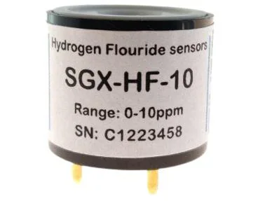
The lab set-up. The plastic tubing from the HF detector is venting to the outside through my lab window. Levels up to 10 ppm have been detected by Sensorix HF-10 numerous times. This arrangement sequesters and safely vents any HF gas.to the outside of the lab.
The Hydrogen Fluoride detector assembly sits atop the reactor vessel with gas “bumping” fan switch that moves gas to the sensor inlet port from the reactor vessel. Surplus HF gas is evacuated from the apparatus ensemble via the plastic conduit to the outdoors.

The PZT discs are interlaced between the carbon electrode discs and are then pre-loaded with a substantial compressive force by a center bolt.
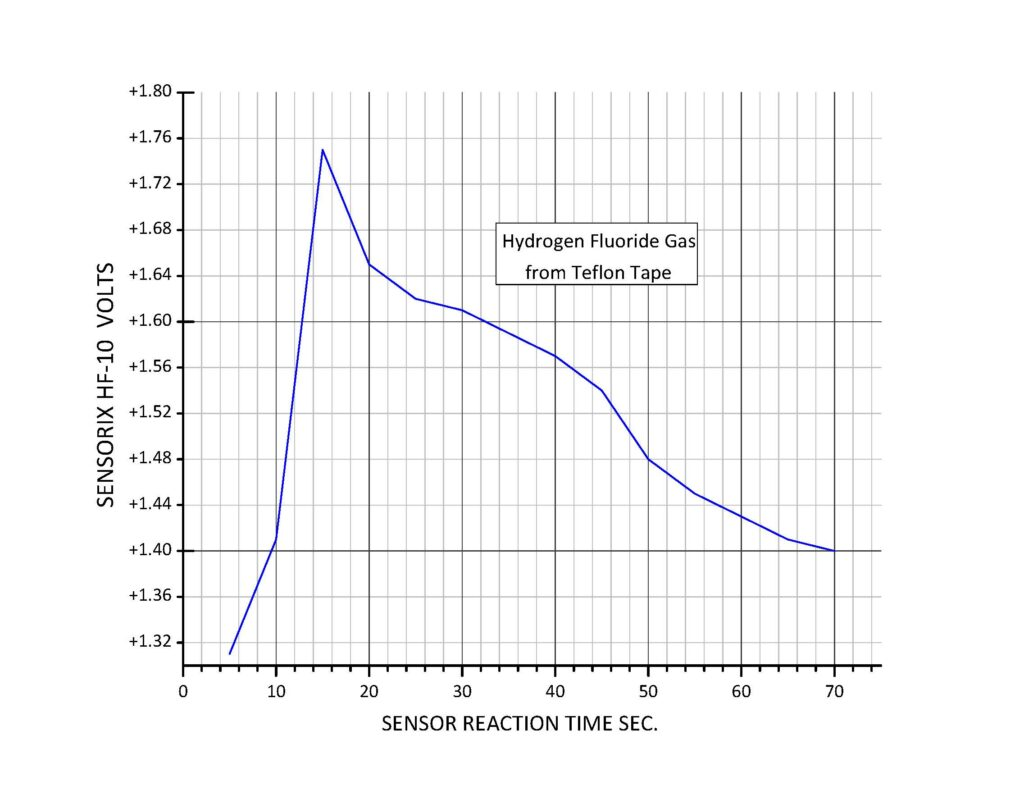
The Hydrogen Fluoride Detector is SGX-HF 10 from Sensorix, Amphenol GmbH. The HF marker gas shows it’s presence in ppm as in the graph mapped over 90 sec. in real time It is calibrated at 1 ppm of HF = 0.40 mV. and has a “cooking” response time of about 1 to 3 seconds. Hydrogen fluoride can only originate from the Teflon tape which is PTFE and serves well to validate the PFAS C-F molecular bond cleavage.

Block diagram of the lab set-up for the validation of the physics. The lab equipment is standard over the counter technology.
